Quadrature DecoderFPGAs are suitable to create quadrature decoders.
What are quadrature signals?
Quadrature signals are two signals generated with a 90 degrees phase difference. They are used in mechanical systems to determine movement (or rotation) of an axis.
Here's one axis moving forward by a few steps.

If you count the pulses, you can say that the axis moved by 3 steps.
If you count the edges, you can say that the axis moved by 12 steps. That's what we do on this page.
Now the axis is moving backward by the same amount.

So the idea is that by looking at the edges and levels, we can determine the direction and distance of movement.
Here's an example where an axis moves forward 10 steps, then backward 7 steps.
![]()
Where are they used?
- In robotic axles, for feedback control.
- With knobs, to determine user input.
- In computer mice, to determine the direction of movement.
If you open a mechanical mouse, here's what you can see.
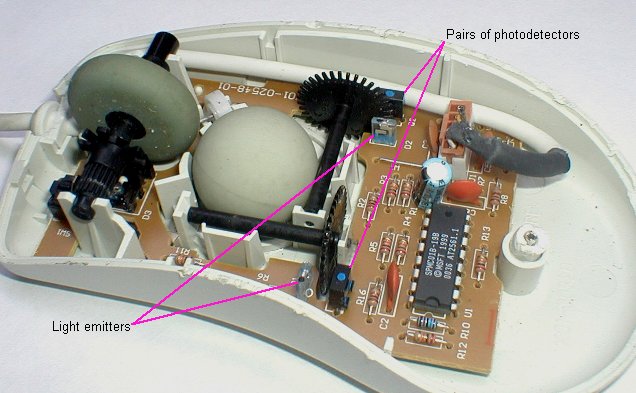
There are two optical quadrature encoders, each made from a slotted wheel, a light emitter and a pair of photodetectors.
The mouse includes an IC responsible for the quadrature decoding and the serial/PS2 interface. Since it is easier to create a quadrature decoder (in an FPGA) than a serial or PS2 interface, we modified the mouse and replaced the original IC with a quad-buffers Schmitt trigger inputs IC.
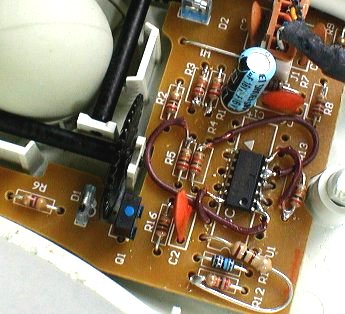
We used a CD4093 with the inputs of the each NAND gate tied together to form inverters.
Now the mouse outputs a quadrature encoded signal!
Quadrature decoder
We want to implement a counter that increments or decrements according to the quadrature signals. We assume that we have available an "oversampling clock" (named "clk" in this page) that is faster than the quadrature signals.
The hardware circuit that controls the counter is surprisingly simple to do.
Here's a waveform where an axis moves in forward direction, so that the counter increments.
This circuit is sometimes called a "4x decoder" because it counts all the transitions of the quadrature inputs.
In verilog HDL, that gives us:
| module quad(clk, quadA, quadB, count); input clk, quadA, quadB; output [7:0] count; reg quadA_delayed, quadB_delayed; always @(posedge clk) quadA_delayed <= quadA; always @(posedge clk) quadB_delayed <= quadB; wire count_enable = quadA ^ quadA_delayed ^ quadB ^ quadB_delayed; wire count_direction = quadA ^ quadB_delayed; reg [7:0] count; always @(posedge clk) begin if(count_enable) begin if(count_direction) count<=count+1; else count<=count-1; end end endmodule |
Real life circuit
The previous circuit assumed that the "quadX" inputs were synchronous to the "clk" clock. In most cases, the "quadX" signals are not synchronous to the clock. The classical solution is to use 2 extra D-flipflops per input to avoid introducing metastability into the counter.
| module quad(clk, quadA, quadB, count); input clk, quadA, quadB; output [7:0] count; reg [2:0] quadA_delayed, quadB_delayed; always @(posedge clk) quadA_delayed <= {quadA_delayed[1:0], quadA}; always @(posedge clk) quadB_delayed <= {quadB_delayed[1:0], quadB}; wire count_enable = quadA_delayed[1] ^ quadA_delayed[2] ^ quadB_delayed[1] ^ quadB_delayed[2]; wire count_direction = quadA_delayed[1] ^ quadB_delayed[2]; reg [7:0] count; always @(posedge clk) begin if(count_enable) begin if(count_direction) count<=count+1; else count<=count-1; end end endmodule |
It takes very little hardware to create a quadrature decoder/counter. An FPGA can hold multiple of them simultaneously and so can keep track of multiple axis rotating simultaneously.
'Enginius > Hardware' 카테고리의 다른 글
| LM257S - 5.0P (2) | 2009.12.11 |
|---|---|
| USB2Serial Driver / ParaniWin (0) | 2009.11.25 |
| 돼지 로봇 소자. (0) | 2009.11.18 |
| Skin sensor / touch tactile sensor (0) | 2009.11.02 |
| 인코더 (0) | 2009.10.28 |
